璟德電子工業股份有限公司
Banner

LTCC Modules
RF Front-end Solutions
Content
Based on LTCC Technology
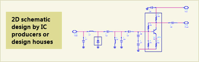
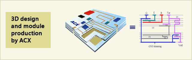
ACX has the ability to produce a variety of RF front-end devices and modules using LTCC technology. We offer in-house LTCC tape systems, which are compatible with DuPont and Ferro tape systems.
LTCC Modules - Foundry Service
Properties of ACX's LTCC material compared with those of commercial materials
| Characteristics | ACX | DuPont 951 | Ferro A6M |
|---|---|---|---|
| Dielectric Constant (@ 3GHz) | 7.5 | 7.8 | 5.9 |
| Dielectric Loss (@ 3GHz) | < 0.33% | 0.43% | 0.20% |
| TCE (25-300°C) (ppm/°C) | 4.7 | 5.8 | 7.0 |
Design Rules
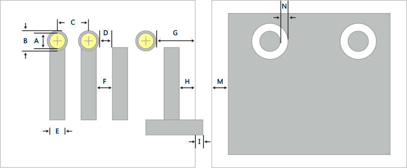
| ITEM | Standard (mm) | Advanced (mm) | |||||
|---|---|---|---|---|---|---|---|
| (A) Via diameter | 0.125, 0.1801 | Flexible (Min. 0.06) | |||||
| (B) Min. via cover pad | ViaØ. + 0.03 | ViaØ. + 0.02 | |||||
| (C) Min. via diameter / pitch (Flip chip) | 0.125/ 0.260 | 0.060 / 0.180 | |||||
| (D) Min. spacing from via cover pad to line | 0.10 | 0.08 | |||||
| (E) Min Line width | Nominal | 0.10 | 0.05 | ||||
| Mean value tolerance | ± 0.015 | ± 0.010 | |||||
| (F) Min. line spacing | 0.10 | 0.08 | |||||
| (G) Min. spacing from via cover pad to substrate edge | 0.15 | 0.10 | |||||
| (H) Min. spacing from conductor to substrate edge | 0.15 | 0.10 | |||||
| (I) Min. dimension for extended terminal | 0.10 | 0.08 | |||||
| (M) Min. spacing from ground plane to substrate edge | 0.15 | 0.10 | |||||
| (N) Feed thru spacing | 0.15 | 0.10 | |||||
| Conductor thickness | Nominal | 0.013 | 0.010 (Fine-line printing) | ||||
| Tolerance | ± 0.003 | ± 0.002 | |||||
| Tape thickness | Without stacked conductors2 | 0.024 | 0.035 | 0.046 | 0.052 | Flexible (Min/Max: 0.015/0.133)3 | |
| 0.094 | 0.104 | 0.129 | 0.147 | ||||
| With stacked conductors | 0.020 | 0.030 | 0.040 | 0.045 | |||
| 0.080 | 0.090 | 0.115 | 0.133 | ||||
| Tolerance3 | Thickness ³0.080 | ± 7 % | ± 5 % | ||||
| Thickness <0.080 | ± 5 % | ± 3 % (Min. ±0.002) | |||||
| Substrate thickness | Max. | 1.6 | 2.4 | ||||
| Min. | 0.5 | 0.3 | |||||
| Tolerance | ±7%(min± 0.075) | ±5%(min ± 0.050) | |||||
| Camber | < 0.3% | < 0.2% | |||||
| Number of layers | Up to 20 | Up to 30 | |||||
| Layer to layer alignment tolerance | ± 0.050 | ± 0.025 | |||||
| Max. panel & array size | Max | 55 x 55 | 110 x 110 | ||||
| Tolerance | ±0.5%(Min. ±0.200) | ±0.2%(Min. ±0.100) | |||||
1All the dimensions are measured after firing.
2Tape thickness is subject to change with stacked conductors at the adjacent areas.
3Based upon the tape thickness with stacked conductors.
footer
CONTACT US

TEL:886-3-5987008
FAX:886-3-5987001
No.165, Hanyang Road, Hsinchu Industrial District, Hsinchu Hsien, Taiwan, 30350
TOP